
Mylar Capacitors

Mylar Capacitors a.k.a polyester capacitors (PET) are special type of capacitors with some unique features compared with ceramic and electrolytic capacitor. They can withstand high voltages in a relatively small package and provides high resistance against moisture.

Pin Configuration

The Mylar Capacitors has no polarity similar to the ceramic capacitors. Meaning they can be connected in any direction. They are breadboard friendly and can be easily used on a perf board also. The symbol for mylar capacitoris just two plain lines as shown above since they do not have any polarity.
Note: There are many types of capacitors; the Mylar capacitor is a special type of capacitor with unique properties  

Mylar capacitor Features

  • Capacitance Range: 0.001uF to 5.6uF
  • Voltage Range: 50V to 630V
  • Tolerance: ±10%
  • Dielectric constant: 3.2 at 1MHz
  • Dissipation factor: 0.5 at 1kHz
  • Capacitance drift: 1.5
  • Operating Temperature:  125°C (max)
Note: More details can be found at datasheet linked below.

What is a Mylar capacitor?

Mylar capacitor is a special type of capacitor right from its construction. As we know as capacitor is nothing but two parallel plates separated by a dielectric medium. The dielectric medium used in this type of capacitor is Polyester hence it is also called as polyester capacitor. Although there are many types of polyester the term “Polyester” here refers to Polyethylene terephthalate which stands for PET.
Because of this PET the capacitor has some special properties which make it suitable for certain applications. The same is discussed below.

Difference between Mylar/Polyester capacitor and other capacitors

Although the ceramic and the Electrolytic are the most commonly used capacitors, the Mylar capacitor has its own applications because of the following unique properties.  A Mylar capacitor has high dielectric strength; hence we can build high voltage capacitor in a smaller package compared to electrolytic capacitors. These capacitors can also work in high temperatures upto 125°C with very little compromise on the voltage rating.
Unlike electrolytic capacitor the Mylar capacitors have very low ESR (Equivalent series resistance) making it suitable for high frequency filtering applications. Due to the property of Polyester the capacitor can withstand sharp voltage spikes and current pikes.

Applications

  • High frequency filtering applications
  • Outdoor applications where moisture is a problem
  • High voltage/current peaks handling circuits
  • Coupling and De-coupling circuits.
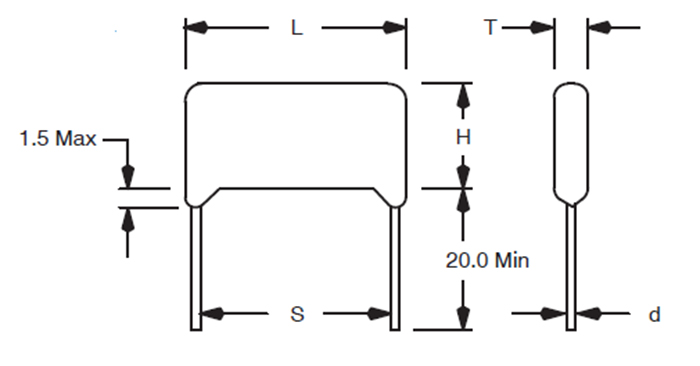
2D-Model

The size of the capacitor depends on the voltage rating of the capacitor. Please refer the mylar capacitor datasheetto know the dimensions of your Mylar capacitor.
Mylar Capacitor 2d-model

Comments

Popular posts from this blog

Coupling

AC Coupling : AC coupling consists of using a capacitor to filter out the DC signal component from a signal with both AC and DC components. The capacitor must be in series with the signal. AC coupling is useful because the DC component of a signal acts as a voltage offset, and removing it from the signal can increase the resolution of signal measurements. AC coupling is also known as capacitive coupling. DC Coupling:  DC coupling allows both AC and DC signals to pass through a connection. When using DC coupling, no additional capacitor is added to filter the signal. The DC-coupled configuration is usually best if the signal source has only small amounts of offset voltage, less than ±100 mV, or if the DC content of the acquired signal is important. Download Excel Simulator

Voltage booster from 1.5 to 12 volt

Lighting up 12 volt LED strip with 1.5 volt battery This is a simple voltage booster circuit. It can increase the voltage of a power source by changing the constant low voltage signal into a series of rapid pulses at a higher voltage. You most commonly see this kind of circuit used to power LEDs with a “dead” battery, but there are many more potential applications for a circuit like this. Any NPN transistor like BC547 1K Resistor 12 Volt LED strip Enamel coated Copper wire preferable SW32 Ferite Ring You can source Ferite ring from dead CFL Bulb Please check out below demo Background: How Does a it Work? This circuit is a self-oscillating voltage booster. It takes a steady low voltage signal and converts it into a series of high frequency pulses at a higher voltage.  Here is how a basic it works, step by step: 1. Initially the transistor is off. 2. A small amount of electricity goes through the resistor and the first coil to ...

Impedance

Input Impedance is the impedance offered by the input terminals of a circuit. It is also defined as the ratio of voltage across the input terminals to the current flowing through the input terminals. Generally we prefer high input impedance over low input impedance .There will be no voltage drop across the source impedance when input impedance is assumed to be infinity.  Output impedance being low is needed because a speaker is 2 ohms, or 4 ohms or 8 ohms or 16 ohms. All of these numbers are very low numbers.This is the output impedance you must match. Input impedance must be high to not “pull” on the source device. For example, a record player, or phonograph, puts out only mini-volts of voltage. So the signal is very weak before it hits the first pre-amp stage. Therefore, you can’t “pull” on that device, since the first stage in any amplifier is basically a voltage amplification circuit and then followed by power amplification circuit. Impedance  formula Z=R2+(Xl...